How to Begin Implement IEEE 802.1Q VLAN Tagging in NS3
To stimulate the IEEE 802.1Q VLAN (Virtual LAN) Tagging project using NS-3 has been includes the replicate of network in which the congestion is segmented for improve the segregation of security and management the congestion. Here’s a step-by-step guide to begin:
Steps to Begin Implementing a IEEE 802.1Q VLAN Tagging Projects Using NS3
- Understand IEEE 802.1Q VLAN Tagging
Key Features of VLAN Tagging:
- Traffic Segmentation: Congestion for segregates network according to their VLAN IDs.
- VLAN Tag: It consider the Enhances for 4-byte header of Ethernet frames
- VLAN ID: The 12-bit field for classifying the VLAN (0–4095) in VLAN ID.
- Priority Code Point (PCP): The PCP has 3-bit field for prioritization of congestion.
- Trunk Ports: Transmit the traffic for several VLANs in trunk ports.
- Access Ports: The access ports are transferring the congestion for a single VLAN.
- Define Project Objectives
Choose the aim the VLAN for denotes the replication simulation:
- It replicates the VLAN-based segregation for congestion.
- We examine the VLAN performance metrics for sample throughput, delay.
- Research through several VLAN for setting for instance trunk vs. access ports.
- Install and Set Up NS-3
- Install NS-3: Download the latest version from the NS-3 website.
- Familiarize by related components:
- BridgeHelper: Intended for the replicate of switches is BridgeHelper.
- Point-to-Point: The Point-to-Point is designed for the wired connections.
- Design the VLAN Architecture
Key Components:
- Switches (Bridge): we replicate the layer 2 VLAN for switching.
- Trunk Ports: Link the switches and transmit the congestion for several VLANs.
- Access Ports: This port is associate the end devices for allocate the detailed VLANs.
- Traffic Model: It replicate the communication in through VLANs.
- Implement the Simulation
Step A: Create Nodes
We generate a nodes for hosts and switches.
NodeContainer hosts, switches;
hosts.Create(6); // 6 End devices
switches.Create(2); // 2 Switches
Step B: Configure VLANs
- Assign VLAN IDs:
- It split the hosts in VLANs for allocate the ID’s.
uint16_t vlan1 = 10; // VLAN 10
uint16_t vlan2 = 20; // VLAN 20
- Map Hosts to VLANs:
- Setting the hosts by detailed the VLAN IDs mention using the frames.
Step C: Connect Hosts to Switches
Use Point-to-Point links to simulate connections.
PointToPointHelper pointToPoint;
pointToPoint.SetDeviceAttribute(“DataRate”, StringValue(“1Gbps”));
pointToPoint.SetChannelAttribute(“Delay”, StringValue(“2ms”));
NetDeviceContainer hostDevices, switchDevices;
// Connect Hosts to Switch 1
for (uint32_t i = 0; i < 3; i++) {
NetDeviceContainer link = pointToPoint.Install(hosts.Get(i), switches.Get(0));
hostDevices.Add(link.Get(0));
switchDevices.Add(link.Get(1));
}
// Connect Hosts to Switch 2
for (uint32_t i = 3; i < 6; i++) {
NetDeviceContainer link = pointToPoint.Install(hosts.Get(i), switches.Get(1));
hostDevices.Add(link.Get(0));
switchDevices.Add(link.Get(1));
}
// Connect Switches
NetDeviceContainer interSwitchLink = pointToPoint.Install(switches.Get(0), switches.Get(1));
Step D: Configure VLAN Tagging
Use the tool NS-3’s BridgeHelper for ensures the VLAN tagging.
BridgeHelper bridge;
NetDeviceContainer switch1Bridge = bridge.Install(switches.Get(0), switchDevices);
NetDeviceContainer switch2Bridge = bridge.Install(switches.Get(1), switchDevices);
Step E: Install Internet Stack
Install the Internet stack for all hosts in the IP communication.
InternetStackHelper internet;
internet.Install(hosts);
Ipv4AddressHelper ipv4;
ipv4.SetBase(“10.1.1.0”, “255.255.255.0”);
ipv4.Assign(hostDevices);
Step F: Add Traffic Applications
- Install Traffic Source:
- Use the congestion source like OnOffApplication for replicate the VLAN-detailed congestion.
OnOffHelper onOff(“ns3::UdpSocketFactory”, InetSocketAddress(Ipv4Address(“10.1.1.4”), 9));
onOff.SetAttribute(“DataRate”, StringValue(“500Mbps”));
onOff.SetAttribute(“PacketSize”, UintegerValue(1024));
ApplicationContainer app = onOff.Install(hosts.Get(0)); // Host 0 in VLAN 10
app.Start(Seconds(1.0));
app.Stop(Seconds(10.0));
- Install Traffic Sink:
- Use the congestion PacketSink for congestion received.
PacketSinkHelper sink(“ns3::UdpSocketFactory”, InetSocketAddress(Ipv4Address::GetAny(), 9));
ApplicationContainer sinkApp = sink.Install(hosts.Get(4)); // Host 4 in VLAN 20
sinkApp.Start(Seconds(1.0));
sinkApp.Stop(Seconds(10.0));
- Configure Simulation
It configures duration of replication and replicates the implement.
Simulator::Stop(Seconds(15.0));
Simulator::Run();
Simulator::Destroy();
- Evaluate Performance
- Metrics:
- It calculates the throughput, delay, and traffic isolation.
- Visualization:
- Use NetAnim for visualization.
- It examine in Python or MATLAB for transfer outcomes.
- Advanced Features
- Dynamic VLANs:
- It replicate the dynamic VLAN membership by 802.1x.
- Trunk Ports:
- Setting the trunk ports for carry the congestion in several VLANs.
- QoS:
- It can use PCP bits for congestion prioritization.
- Inter-VLAN Routing:
- Ensure the communication among VLANs using a Layer 3 router.
Sample Complete Code Framework
#include “ns3/core-module.h”
#include “ns3/network-module.h”
#include “ns3/internet-module.h”
#include “ns3/point-to-point-module.h”
#include “ns3/bridge-module.h”
#include “ns3/applications-module.h”
using namespace ns3;
int main() {
// Create Nodes
NodeContainer hosts, switches;
hosts.Create(6); // 6 End devices
switches.Create(2); // 2 Switches
// Point-to-Point Links
PointToPointHelper pointToPoint;
pointToPoint.SetDeviceAttribute(“DataRate”, StringValue(“1Gbps”));
pointToPoint.SetChannelAttribute(“Delay”, StringValue(“2ms”));
NetDeviceContainer hostDevices, switchDevices;
// Connect Hosts to Switch 1
for (uint32_t i = 0; i < 3; i++) {
NetDeviceContainer link = pointToPoint.Install(hosts.Get(i), switches.Get(0));
hostDevices.Add(link.Get(0));
switchDevices.Add(link.Get(1));
}
// Connect Hosts to Switch 2
for (uint32_t i = 3; i < 6; i++) {
NetDeviceContainer link = pointToPoint.Install(hosts.Get(i), switches.Get(1));
hostDevices.Add(link.Get(0));
switchDevices.Add(link.Get(1));
}
// Connect Switches
NetDeviceContainer interSwitchLink = pointToPoint.Install(switches.Get(0), switches.Get(1));
// Configure Bridge (Switch) with VLAN
BridgeHelper bridge;
NetDeviceContainer switch1Bridge = bridge.Install(switches.Get(0), switchDevices);
NetDeviceContainer switch2Bridge = bridge.Install(switches.Get(1), switchDevices);
// Install Internet Stack
InternetStackHelper internet;
internet.Install(hosts);
Ipv4AddressHelper ipv4;
ipv4.SetBase(“10.1.1.0”, “255.255.255.0”);
ipv4.Assign(hostDevices);
// Install Traffic Applications
OnOffHelper onOff(“ns3::UdpSocketFactory”, InetSocketAddress(Ipv4Address(“10.1.1.4”), 9));
onOff.SetAttribute(“DataRate”, StringValue(“500Mbps”));
onOff.SetAttribute(“PacketSize”, UintegerValue(1024));
ApplicationContainer app = onOff.Install(hosts.Get(0)); // Host 0 in VLAN 10
app.Start(Seconds(1.0));
app.Stop(Seconds(10.0));
PacketSinkHelper sink(“ns3::UdpSocketFactory”, InetSocketAddress(Ipv4Address::GetAny(), 9));
ApplicationContainer sinkApp = sink.Install(hosts.Get(4)); // Host 4 in VLAN 20
sinkApp.Start(Seconds(1.0));
sinkApp.Stop(Seconds(10.0));
// Run Simulation
Simulator::Stop(Seconds(15.0));
Simulator::Run();
Simulator::Destroy();
return 0;
}
Here’s we deliver, how you can replicate the basic IEEE 802.1Q VLAN tagging in ns3 simulation environment that control where nodes interact with each other. If you have any query concerning the above simulation process we will provide it.

 Click Here to watch our latest output video using NS3 simulator
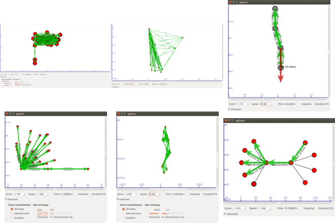
  Click Here to watch our latest projects screenshots using NS3 simulator